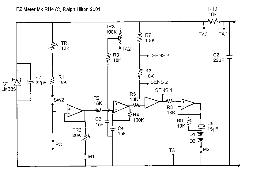
1. The voltage reference for the
bridge circuit is simplified.
2. The meter biasing has been adjusted to use a standard 0 - 100ľA meter
rather then the custom movement required in the Mk2.
3. The circuit now uses a readily available
LM324 op amp rather than the more expensive and sometimes hard to obtain
OP420.
4. The circuit
includes amplification for the meter speed making it possible to use an
off-the-shelf movement rather than a custom made high speed one.

The diodes are any silicon signal
diode.
The circuit
can be used for 1 or 2 meter movements. If one just uses 1 meter then TR2 is
omitted and the high end of the TA pot goes to the point marked TA3. For a dual
dial meter a multiturn pot can be used. If a 3 turn pot is available then
connect the high end to TA3. If only 10 turn is available then try TA3 and TA4
to see which works best for you.
The TA pot should be 20k wirewound and the
sensitivity pot 50k.
For normal use with 2 cans SW2 can be shorted. If one wants automatic
retrimming for solo cans or fingertip electrodes then swith in values of 22k and
39k respectively.
A suitable meter is available
at
http://www.sew.com.tw/st-150.htm
I would use a taut band movement.
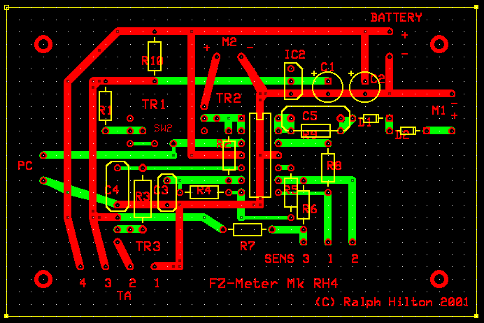
I'll be making up printed circuit boards. These should be available in the near future.
For the adventurous who want to do their own here's a suggested layout. Red for the top layer, green for the underside.
